Have you ever tried to machine a shaft with multiple diameters but ended up with wasted material or undesired shoulders? Step turning is a specialized machining process that solves this exact problem. In this blog post we will explain how this simple lathe method optimizes multi diameter parts. We will also cover its setup and tooling along with an aerospace example.
What Is Step Turning?
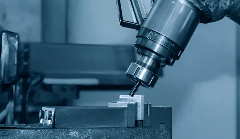
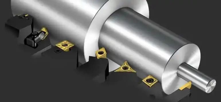
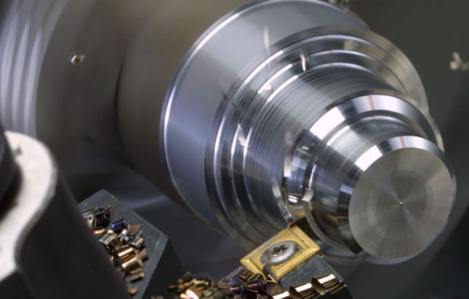
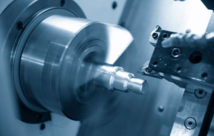
In step turning, a lathe machine turns a cylindrical part into discrete sections(steps) of differing diameter. Each step forms a crisp 90° shoulder. Designs requiring several tightly controlled diameter zones—such as rods and shafts—depend on this method.
Related Blogpost: A Complete Guide to CNC Turning
Step Turning Process Workflow
1. Workpiece Setup
Securing the raw material is the first step in the operation. In most jobs, the stock is a hollow or round bar. Operators clamp this bar tightly inside the lathe’s chuck. Here perfect centering of the setup is essential. This precise centering eliminates misalignment and wobble. Once clamped, technicians zero the machine’s reference points. Zeroing assures that every subsequent cut remains accurate.
2. Initial Facing and Rough Cylindrical Turning
This operation begins with a facing cut that squares the workpiece’s end. That single pass leaves a reference surface which is clean & flat. A rough turning pass then runs along the full length of the bar. This pass strips away scale and other surface inconsistencies.
3. Step by Step Diameter Turning
With the bar roughed, the operator begins machining the individual steps. Cutting usually starts at the end furthest from the chuck and progresses toward chuck. This outward to inward sequence reduces deflection and preserves accuracy. For every step machinists may choose one heavy cut or several lighter passes according to material behavior.
Depth of cut per pass generally lies between 0.5 mm and 2 mm. Use perpendicular tool movements to form crisp 90 degree shoulders between adjacent diameters.
4. Surface Finishing
Once the steps are roughly close to size, machinists perform a finishing pass. That lighter pass refines surface quality and locks in the final dimensions. During finishing the feed rate is usually reduced. This slower feed produces a smooth surface on every step and shoulder.
5. Inspection and In Process Measurement
Continuous measurement remains vital at every stage. After each cut technicians verify the diameter with a Vernier caliper or digital micrometer. These in process checks let timely adjustments whenever necessary and make sure that each step meets its specification before work proceeds to the next one.
Required Equipment, Materials and Tools
Selection of proper tools, machines as well as materials is the foundation of a successful step turning job.
Machine Types: Manual vs CNC Lathes
Step turning suits both manual and CNC lathes. With a manual machine, the machinist sets and aligns stops for every diameter change, a demanding job. A CNC unit, on the other hand, reads programmed instructions for lengths and diameters. This automates the sequence and delivers repeatable results.
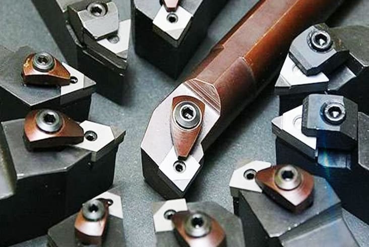
Cutting Tools
A straight shank turning tool is the default choice for cutting down each diameter. Machinists mostly add a parting tool to produce crisp & perpendicular faces where steps meet. When small radii are needed to lower stress concentrations, a tool with a fine rounded nose provides the needed corner relief.
Stock Materials and Machinability
Step turning applies to a wide range of workpiece materials. Typical options are aluminum, brass, steel as well as engineering plastics such as Delrin. Because every material is different, its machinability determines the appropriate feed and speed settings for a clean cut & finish.
Support Accessories
Accurate measurement tools—digital micrometers or calipers—verify every step when tight tolerances apply. Dial test indicators maintain concentricity during setup; and a live center or steady rest supports long shafts to prevent deflection and also to preserve uniform diameters.
Related Blogpost: Special‐shaped Shaft Machining
CNC Step Turning Uses
Because it delivers both precision and efficiency, CNC step turning supports a wide range of industrial fields. The subsections below highlight its primary applications.
Automotive Parts
Automotive manufacturers employ step turning to produce axles, drive shafts and gearbox parts. Several precise diameters of these items let gears, bearings and seals to seat correctly. By holding tight tolerances, the process secures reliable power transmission and lengthens the powertrain’s service life.
Aerospace Equipment
In aerospace plants, accurate shafts for flight critical systems are routinely created with step turning. Landing gear, actuation mechanisms and turbine engine parts receive multiple diameters that satisfy extremely tight fit tolerance zones. Only by meeting such accuracy (that step turning provide) these components survive the intense heat and stress they encounter.
Custom Machined Parts
When projects call for prototypes or custom pieces, step turning offers unmatched repeatability. Engineers turn to it for robotics, medical devices and hydraulic system components. Machining all diameters in one setup delivers extraordinary dimensional accuracy—vital during new design testing and development.
Advantages of Step Turning
Step turning brings a number of notable advantages which make it an efficient and dependable way to machine complicated parts.
Single Setup Multi Diameter Machining
Because every step is machined during one uninterrupted pass, operators avoid all repositioning and reclamping. Consequently alignment and concentricity across every diameter stay exceptionally high.
Lower Cost
Fewer setups shorten the overall cycle and reduce manual involvement. Higher throughput in turn lowers the cost per part and also supports economical production.
Superior Dimensional Accuracy
CNC control routinely holds tolerances as tight as ±0.01 mm. This consistency goes beyond manual turning and is one that sharply limits human error.
Reduced Thermal and Mechanical Distortion
Short & localized cuts generate minimal heat at each shoulder. This keeps internal stresses low and also prevents any warping of the finished component.
Common Limitations and Cautions
Although it has a lot of advantages but still has some challenges.
Excess Material/ Waste Removal
Large diameter differences can create substantial scrap; a serious expense when working with costly metals like titanium. RICHCONN helps reduce this by careful stock selection optimization and also by its machining strategies for every project.
High Setup Accuracy Required
This method demands extremely precise initial alignment of the workpiece. Even slight misplacements—particularly during manual setup—can accumulate across the steps and distort final dimensions.
Post Process Finishing Requirements
Sharp transitions between steps may show tool marks therefore secondary operations such as polishing or manual blending are mostly necessary to alleviate stress and fulfill aesthetic standards.
Best Practices, Tips and Error Avoidance
I. Align and Zero Correctly
A successful step turning starts with careful preparation. First face the stock’s end to generate a flat zero reference. Next verify that the chuck grips the workpiece precisely on center. Even slight misalignment accumulates and distorts step dimensions later.
II. Plan Step Sequence Intelligently
Thoughtful sequencing keeps the setup stable and the results accurate. Normally the machinist removes material from the step farthest from the chuck before touching the others. Roughing passes are usually 2 to 3 mm deep and clear most of the excess metal quickly. Afterwards a light finishing cut of 0.2 to 0.5 mm brings the part to size and polishes the surface.
III. Minimize Shoulder Blending Issues
Visible tool marks mostly appear where steps meet at a sharp corner. When the design permits, include a corner radius of 1 mm or smaller to soften the transition. That minor change not only improves the blend but lowers stress at the corner as well. This makes the part stronger.
IV. Reduce Scrap
Select stock whose diameter nearly matches the largest step on the drawing. Doing so becomes critical whenever adjacent steps differ by more than 20 mm. The proper starting size limits tool wear, slashes machining time as well as cuts material waste.
Case Study-Step Turning an Aerospace Grade Stepped Shaft
Project Overview
For this case study our team examined how to design and CNC machine a stepped shaft destined for an aerospace actuator. Starting with a solid cylindrical billet we needed to generate a precise profile that included a number of diameters and clean step transitions. Because the shaft fits into a flight critical assembly, tight tolerances, extraordinary surface finish and consistent repeatability were non‐negotiable.
Part Description
- Material: Titanium Grade 5 (Ti-6Al-4V)
- Stock Dimensions: Ø60 mm × 200 mm
- Final Shape: Stepped cylindrical shaft with 4 diameter changes
- Step Features:
- Ø60 mm → Ø45 mm at Z = −40 mm
- Ø45 mm → Ø30 mm at Z = −80 mm
- Ø30 mm → Ø25 mm at Z = −120 mm
Such a profile is typical for aerospace shafts that must carry several bearing or gear seats along one axis.
Machining Strategy
a. Machine Setup
- Machine: Haas ST 20 CNC Lathe
- Controller: Fanuc compatible
- Tooling: Right hand turning tool with carbide insert (T01)
- Workholding: 3 jaw chuck with soft jaws for concentricity control
- Work Offset: G54 referenced at the raw stock face (Z = 0)
b. Programming Approach
Programming relied on G90 absolute positioning while the control ran in G21 metric mode. We wrote each turning pass manually for every step; because it is the method that preserved clarity and gave full authority over the transitions.
c. Cutting Parameters
- Spindle Speed: 800 RPM (G97)
- Feed Rate: 0.25 mm/rev (G01)
- No canned cycles are used for maximum path control
G Code Implementation
Here is the core turning code that we used to manufacture the part:
O1001 (STEP TURNING – AEROSPACE SHAFT)
G21 (METRIC UNITS)
G90 (ABSOLUTE POSITIONING)
G40 G80 G99
G18 (XZ PLANE)
(TURNING TOOL T01)
T0101
G54 (WORK OFFSET)
G97 S800 M03 (SPINDLE ON CLOCKWISE, 800 RPM)
G00 X65.0 Z2.0 (RAPID TO STARTING POSITION)
(CUT Ø60 TO Ø45 STEP, Z0 TO Z-40)
G01 X60.0 Z0.0 F0.25
Z-40.0
X45.0
(RAPID TO NEXT DIAMETER)
G00 X65.0 Z-40.0
(CUT Ø45 TO Ø30 STEP, Z-40 TO Z-80)
G01 X45.0 F0.25
Z-80.0
X30.0
(RAPID TO NEXT DIAMETER)
G00 X65.0 Z-80.0
(CUT Ø30 TO Ø25 STEP, Z-80 TO Z-120)
G01 X30.0 F0.25
Z-120.0
X25.0
(RETRACT AND SPINDLE STOP)
G00 X100.0 Z100.0
M05
(END OF PROGRAM)
M30
Simulation and Verification
We verified the G code inside Fusion 360 CAM’s simulation environment and again with NC Viewer:
- Every toolpath followed transitions b/w steps exactly as planned.
- No gouging or collisions appeared.
- Diameter changes remained clean and fully controlled.
Results
- Cycle time averaged roughly 3.5 minutes, counting setup or tool swaps not included.
- The surface reached an Ra of 1.6 µm with no extra finishing steps.
- All diameters held ±0.02 mm.
- Five parts were produced and every one cleared inspection.
Step Turning vs Taper Turning, Facing and Grooving
| Operation | Primary Goal | Tool Movement | Resulting Shape |
|---|---|---|---|
| Step Turning | Generate several discrete diameters along one workpiece. | The tool first advances along the axis and then move radially to form a step. | Produces a stair step profile defined by sharp 90 degree shoulders. |
| Taper Turning | Deliver a smooth & continuous diameter change along the part. | The cutting edge travels along a path angled to the axis. | Creates a uniform conical surface. |
| Facing | Flatten the workpiece end and machine it to particular length. | The tool sweeps radially across the face & perpendicular to the axis. | Leaves a smooth as well as flat end surface. |
| Grooving | Cut a narrow recess or channel into the material. | Tool plunges straight in, radially at single position. | Yields a narrow slot of defined width and depth. |
Because RICHCONN performs every one of these lathe operations in house, you can get all turning and finishing services under a single roof if you choose us.
To Sum Up
In short manufacturers can machine components with several diameters proficiently in one setup by using step turning. Compared with running several operations this technique cuts expenses, boosts accuracy and also limits scrap material.
If you need precise & dependable step turned parts then Richconn is your best option. You can contact us anytime.
Related Questions
Feed & cutting speed must match the workpiece material. Softer alloys accept faster spindle speeds whereas harder metals call for slower settings. Generally set roughing feeds between 0.005 and 0.020 in/rev and finishing at 0.002 to 0.004 in/rev.
Step turning normally involves a lathe with turning and parting tools and measuring devices like micrometers or Vernier calipers.
Custom step turned components are available at precision machining shops. Choose providers who guarantee tight tolerances, diverse surface finishes, multiple material options and quick delivery. Richconn meets each of these criteria at a relatively good price therefore you can trust us.