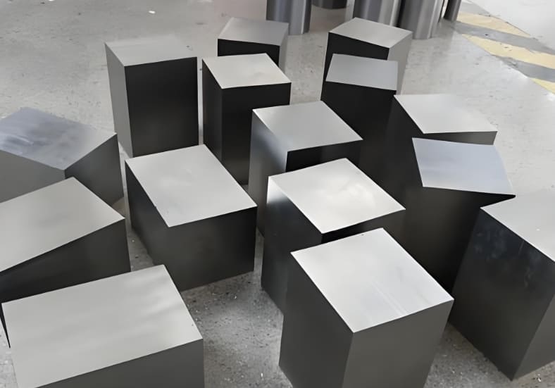
In manufacturing, jigs and fixtures are crucial for precision, speed & safety. When you master their design you can reduce costs, improve quality and make production more efficient.
In this blog post you will find design principles, types, workflow, real world examples and best practices. In short you will get all the information you need to design jigs and fixtures.
What are Jigs and Fixtures?
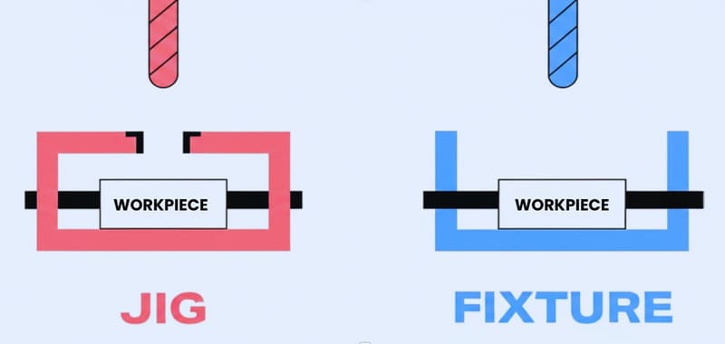
In simple terms jigs and fixtures are specialized tools to increase speed and accuracy in manufacturing. A jig holds the workpiece and directs the cutting tool as well. This makes it ideal for tasks like tapping or repetitive drilling. By guiding the tool a jig assures every hole is in the right place.
A fixture, on the other hand, only holds the workpiece firmly while the tool moves around it. Fixtures are fundamental for grinding or milling where the workpiece needs to be stable.
You can see the main differences between jigs & fixtures in the table below:
| Feature | Jig (Guides Tool) | Fixture (Holds Workpiece) |
|---|---|---|
| Tool Guidance | Yes | No |
| Workholding | Yes | Yes |
| Weight | Lighter | Heavier |
| Complexity | More complex | Simpler |
| Typical Use | Drilling, tapping | Milling, grinding |
Basic Design Principles for Jigs and Fixtures Explained
To get both efficiency and accuracy in manufacturing you need to understand the basic principles of jig and fixture design.
1. Accuracy and Repeatability
Jigs and fixtures must always position parts in the same place. In this way every product will be of the same shape and size, which reduces defects and errors.
2. Locating Systems
Locating devices keep the workpiece exactly where it should be. The 3-2-1 method, which uses six points, is common for positioning. By restricting nine degrees of freedom this method keeps the part stable and properly oriented during machining.
3. Clamping and Support
Clamps hold the workpiece tight and resist cutting forces. Supports stop vibration or bending so the part stays in position and shape.
4. Guiding Mechanisms
Guides make sure tools like drills move along the right path. This assures cuts and holes are in the right place which improves consistency and quality.
5. Tool Body Design
The main body of the tool should be strong but not too heavy. It should support all components, withstand repeated use and let the operator move it easily.
6. Material Selection
Choose steel, aluminum or cast iron based on cost and strength. Durable materials mean your tools will last longer and need less maintenance.
If you’re unsure which material best suits your application, working with an experienced manufacturing partner like RICHCONN can help you balance cost, performance and manufacturability. It is particularly important when your project involves custom plastics, metals or even carbon fiber parts.
7. Fool proofing and Ergonomics
Design parts so they only go one way to prevent mistakes. Make handles comfortable and controls within easy reach for safe & efficient operation.
8. Modularity and Standardization
Use standard parts and modular design that you can swap quickly for different tasks. This will save you time & money in the long run.
9. Affordability and Lifespan
Look beyond the initial build. Design for long lifespan, easy maintenance and fast part changes. This way you will get the most out of your investment throughout the tool’s life.
Types of Jigs and Fixtures
Manufacturing works need jigs & fixtures that match the specific application as well as the shape of workpiece.
Types of Jigs
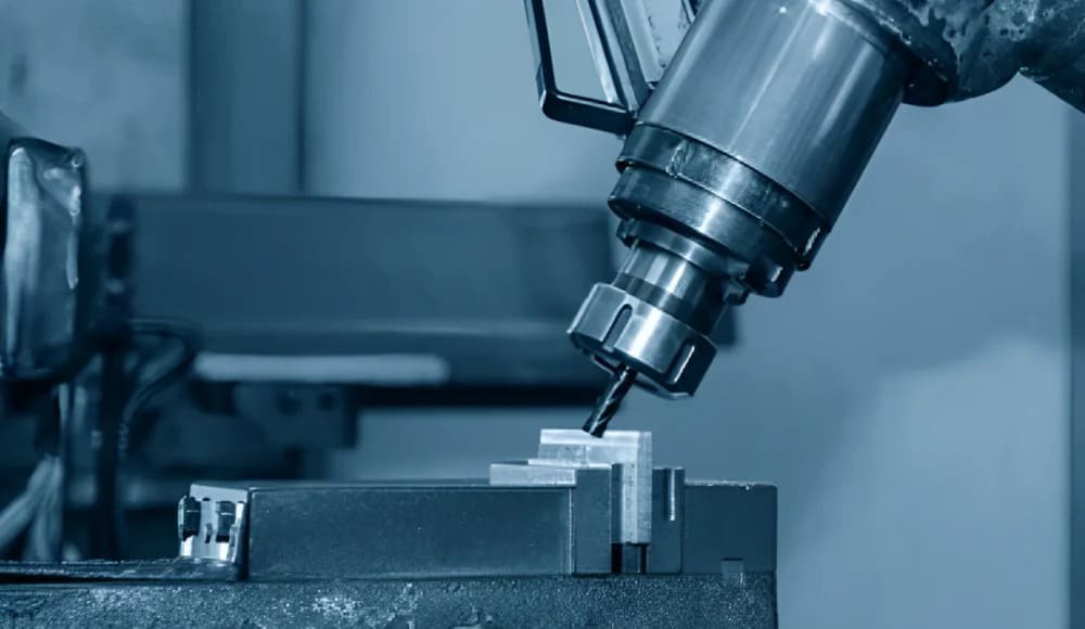
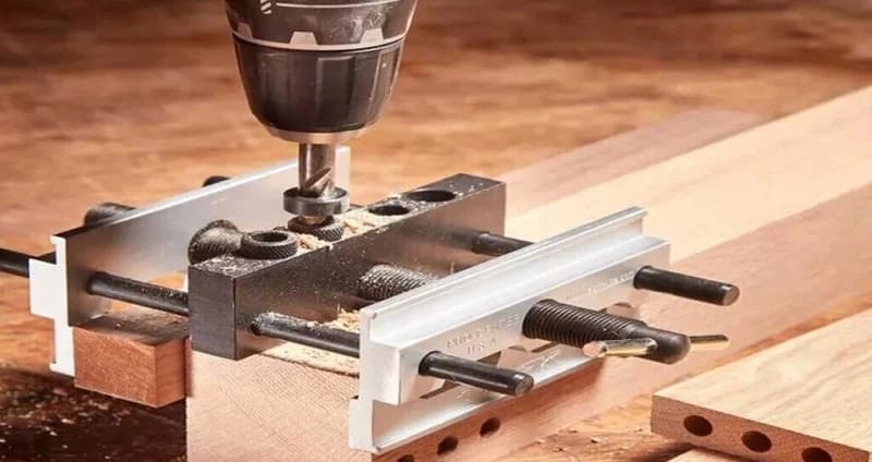
Drill Jig
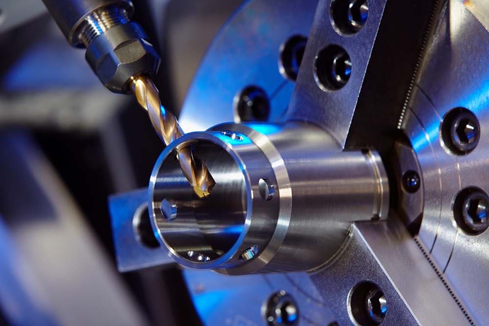
Drill jigs guide taps, drills or reamers with high accuracy. They hold the workpiece in place and set its position. Use them when you need to make the same hole many times.
Template Jig
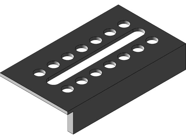
Template jigs use a plate with pre made holes to guide the tool. This is the simplest type and is best for small batches or when you want to copy hole patterns quickly and with precision.
Plate Jig
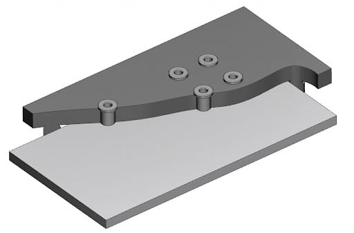
Plate jigs improve on template jigs by adding drill bushes for better accuracy. They are most useful when you need to drill several holes in flat or large parts.
Channel Jig
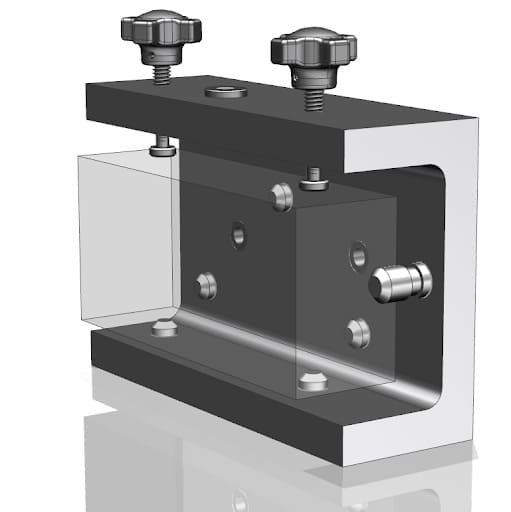
Channel jigs have a U‐shaped cross section. The workpiece fits inside this shape. These jigs are good for narrow or long parts because they clamp tightly and guide tools easily.
Types of Fixtures
Milling and Turning Fixtures
Milling fixtures keep workpieces stable during milling. They absorb vibration and help you get accurate cuts.
Turning fixtures hold parts on lathes as they rotate. These are best for machining cylindrical or round shapes.
Welding and Assembly Fixtures
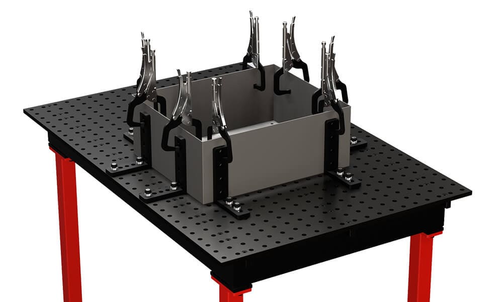
Welding fixtures keep parts aligned and stop distortion during welding. Assembly fixtures hold parts together for mechanical joining. These fixtures speed up repetitive builds and help you maximize consistency.
Drilling, Broaching, Grinding and Boring Fixtures
Drilling fixtures guide the drill to place holes precisely. Broaching fixtures keep parts steady for linear cutting. Grinding fixtures hold parts in place for surface finishing. And boring fixtures support accurate enlargement of holes.
Duplex (Multi Station) Fixtures
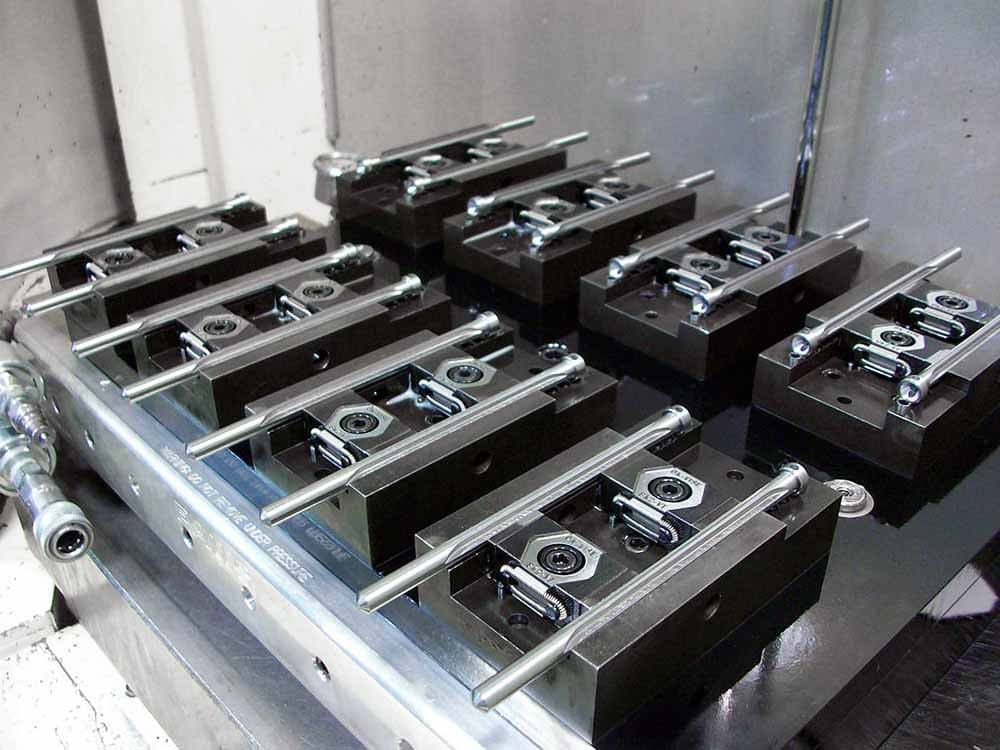
Duplex fixtures let you machine two identical parts at different stations at the same time. This setup increases throughput and efficiency. It also reduces setup and changeover time which is valuable in high volume production.
Hybrid and Advanced Fixtures
Adaptive Pin Array Fixtures
Adaptive pin array fixtures use movable pins to match many shapes. They are good for holding irregular or complicated parts. This design increases flexibility in your production procedure.
Snapping Fixtures
Snapping fixtures have flexible fingers which “snap” around a part. You can set them up quickly and without tools. They are ideal for custom or delicate items.
Core Components and Hardware
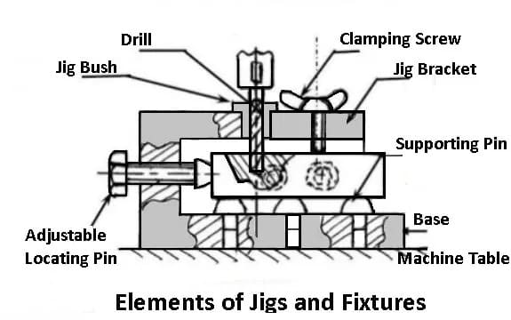
1. Tool Body/Base
Every jig or fixture relies on the tool body for strength. Manufacturers mostly use cast iron, aluminum or steel to build it. This component forms the base on which all other parts get attached.
2. Clamps and Supports
Clamps hold the workpiece in place during machining. Manual clamps are affordable and simple. For faster cycles in high volume production hydraulic or pneumatic clamps work well. Moreover supports like jack screws stop flexible or thin parts from bending.
3. Locators
Locators set the workpiece in the correct position. Some well known options are V locators, pin locators and nest locators.
4. Tooling Plates & Blocks
Tooling plates have threaded grids, like M8 holes spaced at 22.5 mm, for flexible setups. You can move or add clamps and supports as your process requires. This allows you to adapt the fixture for different workpieces and machining tasks.
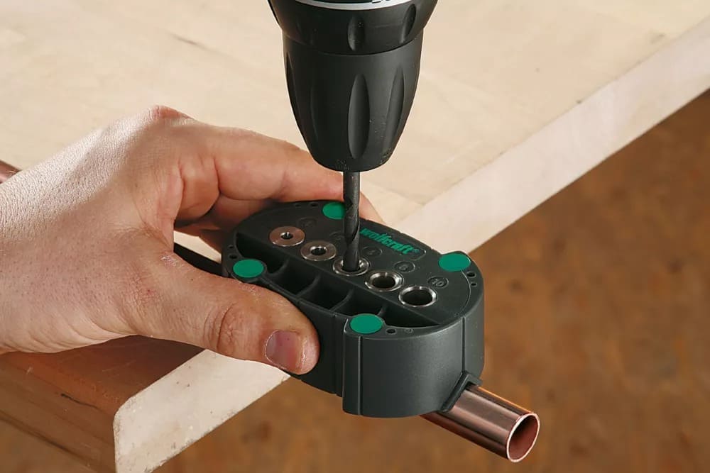
5. Guides and Bushings
Guides & hardened drill bushings help direct cutting tools – especially when used in jigs. These parts keep hole locations consistent and shield tools from wear.
Jig and Fixture Design Process Workflow
Effective jigs & fixtures designing need a step by step procedure.
Define Requirements
Start by looking at tolerance requirements, production volume and the shape of the workpiece. Write down every machining operation and the order they occur.
Conceptual Layout
Then sketch how you will set up the workpiece. Decide where the workpiece will be positioned for best machining results and easy access. At this point think about operator comfort and safety.
Tool Body Modeling
Next build a detailed 3D model of the tool body. Use design software like AutoCAD, SolidWorks or Fusion 360 for this step.
At RICHCONN, our engineers refine every design through thousands of real world projects. This assures that every model is ready for manufacturing.
Locator Placement
Use the 3-2-1 principle to control all six degrees of freedom. Place three locators on the main datum plane, two on the secondary and one on the third. Make sure your locating points match the part datums to keep dimensions accurate.
Clamping Strategy
Choose clamps that hold the part firmly but don’t deform it. Plan where and when to clamp for easy loading & unloading. Use quick‐acting clamps if you want to cut down cycle time.
Guide Integration
Add tool guides and drill bushings to your design. Give bushings enough support so they don’t bend during cutting.
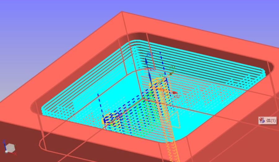
Simulation and FEA
Run finite element analysis if needed to check the tool’s strength and how much it bends. You can use software like SolidWorks Simulation, ANSYS or ABAQUS to analyze stress & deflection.
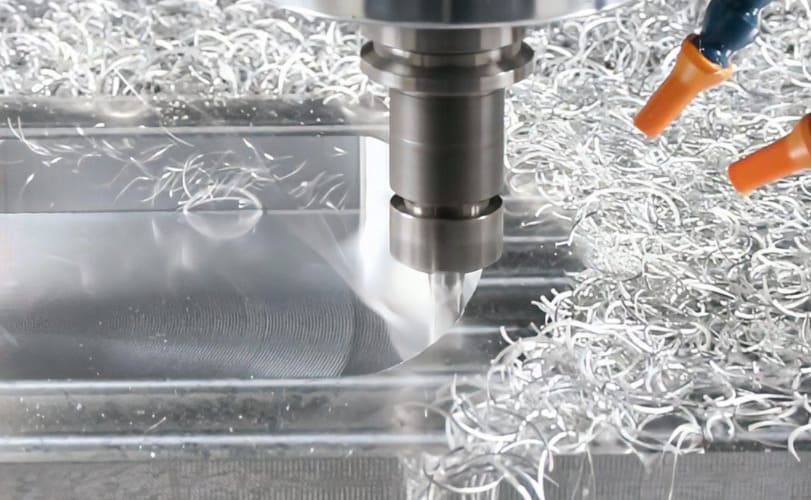
Prototype and Build
Make prototypes with 3D printing for complicated shapes or CNC machining for metal parts. Test the tool before full production. Change your design as needed based on these tests to get the best results.
RICHCONN’s rapid prototyping services with tight tolerances of about ±0.01mm can help you quickly test the fit and function before moving to full production.
Also See: CNC Machining vs 3D Printing_ Which One is Better for You
Validation and Testing
Make sure the tool meets cycle time, accuracy as well as durability needs before full production. Also check operator comfort and safety features.
Checklist Review
Finally review maintenance needs, usability and cost recovery calculations. Make sure all design goals are met before you put the tool into production.
Case Studies
CASE 1: Drill Jig for Aerospace Parts
An aerospace company had to drill hundreds of holes in aluminum panels. To solve this Richconn created a drill jig which used hardened bushings to guide each drill bit. It also used accurate locating pins to assure the panels stayed in the correct position every time. With this jig they reduced rework and improved hole accuracy. This met clients’ demand & quality standards.
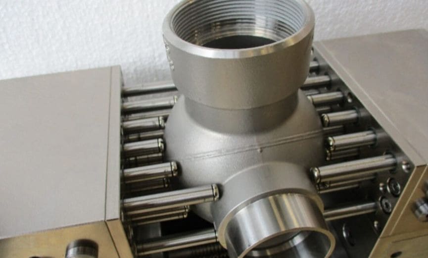
CASE 2: Adaptive Pin‐Array Fixture for Medical Implant Machining
A medical device manufacturer had to machine titanium hip implants with complicated organic shapes. Standard fixtures couldn’t hold these parts.
To solve this Richconn created an adaptive pin‐array fixture with a 20×20 grid of movable pins. Every pin was set individually to match the implant’s shape and then locked in place. This fixture then kept the part stable, avoided distortion and allowed accurate machining of the implants.
Best Practices and Pitfalls
Common Mistakes
- If you clamp the workpiece too tight it will distort and lower the quality of the finished part.
- Not considering tool interference can cause collisions. Both the fixture and the cutting tool may get damaged.
- If you overlook accessibility, operators will struggle to load or unload parts. This increases operator fatigue and cycle time.
Practical Tips
- Use renewable bushings and inserts you can replace. This will extend the life of fixture and reduce downtime.
- Maintain guides and clamps regularly. Consistent maintenance keeps accuracy high and avoids sudden failures.
- Design ergonomic clamps. As you can operate them with one hand and minimal force is needed. Moreover the setup will be safer and faster.
For high precision or complicated projects, it’s worth partnering with a manufacturer early. RICHCONN’s design‐for‐manufacturing consultants often help clients prevent fixture issues before they arise; thus saving both cost and time down the line.
Economic Metrics
Economic factors are important too. Always weigh the cost of the fixture against the cycle time savings you expect.
In high volume production saving just 10 seconds per part can pay for the fixture after a few thousand cycles. If you use standard parts and modular designs you can boost ROI and keep your production procedure efficient.
To Sum Up
In short, jigs guide the tool and fixtures only hold the part. Using both means your work is fast, accurate and of high quality. A well designed jig or fixture resists working forces, controls all movement, keeps operators safe and supports lean manufacturing by saving costs.
If you need any kind of help regarding jigs & fixtures or any other CNC related work then Richconn is your best option. You can contact us anytime.
Related Questions
You will often find strap clamps, screw clamps, swing plate clamps and toggle clamps in modular setups. For locating, common choices are dowel pins, locating pins, pads and V‐locators.
Choose materials with similar thermal properties, leave space for movement and add adjustable parts or expansion joints if needed. This will keep your fixture precise upon temperature change.
AutoCAD, SolidWorks and Fusion 360 are most commonly used for fixture design. For more specialized needs ToolingBoss, FixturePro, JigCAD and NX CAM offer more advanced features for complicated designs.